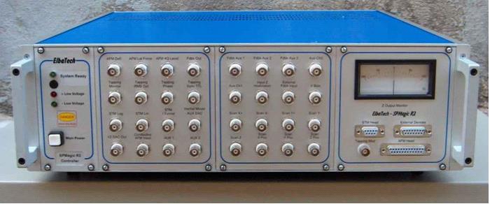
Elbatech SPMコントローラー
SPMagic R2
General specifications
The SPMagic R2 is a low-cost, compact solution intentionally designed as an open, customizable SPM Control System. SPMagic R2 consists of a computer-driven SPM controller equipped with both AFM and STM signal conditioning electronics, capable of implementing further measuring techniques such as SNOM or others. The system can be connected with one of our precision high voltage amplifiers suitable for interfacing home-built as well as commercial measuring heads. The system is a comprehensive instrument which can be used as-it-is (just turn on the power and go !), as well as in a variety of different setups, since all signals are available at the front panel and can be used to customize the setup, even in conjunction with add-on external equipments. The software allows the control of all the available features and directly drives the data acquisition. Extra analog input channels are available for further improving the experimental capabilities.
The SPMagic R2 controller provides different types of XYZ scan signals and can therefore be easily interfaced with many types of High Voltage amplifiers, either choosen among our models or from thirdy part producers. In particular, the system provides outputs directly compatible with most piezoactuator Companies’ standards. Among them we can quote PiezoSystemJena, Physik Instrumente, Staveley sensors Inc and others. We produce our T-100, T-300, T-500, T-700 SPM-devoted HV amplifiers as well as many other models suitable for special piezoelements.
Product highlights.
- All available signals are present at the front panel, which enables easy and fast customization of the experimental setup.
- Full 16 bit data acquisition electronics. The AD/DA sections of the controller are embedded in a PCI card which also provides the system with synchronization and digital I/O signals.
- The scanning ramp technology is based upon a double-DAC system, where a first 16 bit positioning DAC is combined with a second 16 bit scan DAC to maximize the scanning resolution at any scan dimension.
- The controller if fully software-controlled. No front panel switches and pots ! Just open the user interface window or pop up panel dedicated to a certain section and perform all settings and regulations from there.
- New software releases are free and can be downloaded from our web site.
- The flexible software control allows easy and fast setting even when external devices are used for particular experimental setups. In these cases, choose the correct plugs at the front panel, connect them to your equipment and easily switch the signal path from the software program.
- The system allows contact deflection, topography and torsion measurements, as well as tapping mode imaging with the integrated LetItTap module, and force-distance curves. Specific additional measurements can be setup.
- STM measurements are performed using an external, shielded, high precision lin/log current preamplifier, directly connected to the controller STM input.
- An AFM measuring head can be included; it is a compact and flexible solution featuring a four quadrant detection system together with an intensity-regulable laser diode. Plane scan ranges vary from 1×1 μm up to 100×100 μm. Custom ranges are available upon request, just specify the range you need at the order time !
System details
Controlle
Dimensions :19” x 3U x 500mm
Weight :~6 kg
Voltage :230 VAC ± 5%, 50-60 Hz (115 VAC upon request)
Power consumption:<20 W
Connections
Measuring head, standard 25 pin D-type
Power supply input, fuse protected
Computer interface, 2 x high density SCSI-III 68 way
Serial Interface control signals for device expansions (analog supply included), 15 pin D-type
BNC inputs:
external feedback signal 1 (suitable for SNOM and other techniques)
external feedback signal 2
external feedback signal 3
aux analog input channel 1, ±10V vs. GND
aux analog input channel 2, ±10V vs. GND
z-axis piezo actuator modulation
external feedback connection
AFM conducting probe signal
BNC outputs:
feedback output monitor
V bias
AFM deflection (T-B) signal monitor
AFM torsion (L-R) signal monitor
four quadrant photocell sum signal
AFM tapping signal monitor
AFM tapping RMS signal
AFM tapping phase signal
AFM tapping modulation signal
AFM tapping TTL modulation signal
STM log signal
STM lin signal
STM tunneling current monitor
Auxiliary DAC output
Scan X+, ±10V vs. GND
Scan X-, ±10V vs. GND
Scan Y+, ±10V vs. GND
Scan Y-, ±10V vs. GND
Z signal, ±10V vs. GND
Scan X, 0÷10V or -2÷12V (for Physik Instrumente piezo drivers) vs. GND
Scan Y, 0÷10V or -2÷12V (for Physik Instrumente piezo drivers) vs. GND
Scan Z, 0÷10V or -2÷12V (for Physik Instrumente piezo drivers) vs. GND
Z DAC ouput monitor
Resolution
The controller is designed to be interfaced with a National Instruments PCI-6259 or PCI-62-89 multifunction board, where the signal are properly routed from the controller by means of two external cables. The overall performance is detailed below.
AD converter :16 channels, 16 or 18 bit
DA Scan X-Y converters :16 bit
DA Positioning X-Y converters :16 bit
DA Z (force-distance and I-V curves) :16 bit
Laser intensity regulation DAC :12 bit, 0 to 5 mW
AFM
The controller embeds a full AFM controller, both for contact and for tapping mode. The conditioning electronics works on the four signals coming from an external photocell preamplifier and generates the deflection, lateral force and sum signals plus a fast-deflection signal suitable for oscillating modes. Tapping mode is implemented by a dedicated hardware and software with an extremely user-friendly interface allowing for spectrum acquisition of the cantilever oscillation and to set the final working frequency. The module is based on a Direct Digital Synthesizer (DDS), thus ensuring top digital stability and quality of the generated oscillation.
STM
We offer two STM preamplifiers models, respectively indicated for tip-grounded and for samplegrounded experimental setups. Both models allows setting the bias voltage between tip and sample through a software driven 16 bit stable digital to analog converter and feature a gain of 108 (i.e. 1nA input current produces a 100 mV output voltage). The preamplifiers are embedded in a metal chassis for noise immunity and connect to the Controller by means of a single cable. Our preamplifier’s input current range goes from 30 pA to 30 nA in log mode and from 30 pA to 10 nA in linear mode.
Data acquisition
Imaging mode:
5 independent and selectable channels acquired during scanning
image is acquired by rastering, therefore two images per scan are available (forward and backward)
image resolution ranges from 64×64 up to 512×512 pixel, at 16 or 18 bit
scan frequency per line 40 Hz max
selection area is defined by user-friendly drag operations on the user interface
zooming in and out available
Signal mode:
12 independent channels can be acquired
during tip-sample approach, all the necessary signals are monitored and displayed
Force-distance and I-V modes:
the system drives the piezo tube while acquiring input data
eventual modulation signals can be superimposed to the piezo driving signal
Feedback control
Native feedback is analog, fully digitally-controlled. External feedback systems can be easily interfaced to the instrument.
The feedback implements a modified PI(D) controller with additional bandwidth control.
Feedback controls:
input signal setpoint
proportional gain
integral gain
derivative gain
working bandwidth selection
Additional controls for system customization:
feedback input signal sign (positive/negative)
feedback input signal source (choose one of available 8 channels)
feedback output sign (direct/reverse)
feedback controller (internal/external)
HV amplifier (on/off)
Personal computer
The controller works interfaced to a Windows Operating System based Personal Computer running the SPMagic R2 software.
This personal computer must include a National Instrument PCI-6259 or PCI- 6289 multifunction board as indicated in the “Resolution” section above
Operating modes
STM:
Constant current mode
Constant height mode
I-V spectroscopy
AFM:
Constant height mode
Constant force mode
Lateral force mode
Tapping mode
Phase imaging mode
Force-distance spectroscopy
OTHER:
Since SPMagic R2 is a real flexible controller, advanced imaging techniques can be easily set up.
Towards this end the User can utilize all the signals available at the front panel and the related selection functions in the software.
Among these advanced techniques we can quote:
SNOM
Kelvin Probe Microscopy
Magnetic Force Microscopy
Conductive AFM,
Phase-distance
generic signal-distance curves
etc…